Patent us6814104 35 hydraulic system valves pdf Schematic of the electro-hydraulic valve actuation system.
Hydraulic symbology 203 – pressure valves
Hydraulic valve directional control inchbyinch Basic hydraulics Hydraulic system circuit: 1 -motor; 2 -pump; 3 -reservoir; 4 -direct
Pilot-operated unloading valve
Hydraulic unloading valve circuit operationDirectional control valves valve hydraulic dcv pilot mounted ports drain configuration external Hydraulic symbology 203 – pressure valvesPatent patentsuche bilder valve.
Patentsuche bilderHydraulic symbols system drawing circuit engineering diagram pump mechanical simple beginners cylinder fluid pnuematic solenoid valve basic electrical hydraulics symbol Valve hydraulic control spool directional gpm valves float single monoblock joysticks backhoe hydraulics summit p40 p80 individual updatedHydraulic system schematic diagram of experiment platform.

Directional control valves: hydraulic pilot operated four-way
Schematic gridgitHydraulic system for beginners Pressure hydraulic valves circuit symbology relief sequence pump limitValve hydraulic pilot relief operated schematic pressure symbol control valves symbols unloading reducing spring inlet prv troubleshooting.
Control directional hydraulic system basic basics hydraulicsSchematic diagram of hydraulic system Hydraulic pressure valves symbologyWolfram hydraulic valves diagram modeler system language.

Hydraulic basic system aircraft systems examples power gear diagram law schematic hydraulics control landing pascal components down figure mechanical
Hydraulic control valvesValve proportional began Control of a double-acting hydraulic cylinder4 way spool valve schematic symbol, 4, get free image about wiring diagram.
Hydraulic: valves.pressurecontrol.compoundreliefvalveValve hydraulic way pilot operated four schematic control directional valves Motor simplified rig efficiency valve piston directionalPatent us2849987.

Valve hydraulic diagram control way circuit directional position basic
Valve operation clamping punchingHydraulic flow control valves Flow control valve hydraulic diagram pressure compensated valves parker operation dcv 31b reprinted hannifin permission showing figure corpValve unloading pilot pressure operated circuit hydraulic schematic control high.
Hydraulic symbology 203 – pressure valvesHydraulic valve control valves directional basics parts hydraulics gpm spool magister cylinders manufacturer monoblock cylinder post flow magisterhyd repair Hydraulic sequence valve operationHydraulic schematic.

How a hydraulic self-leveling valve works
Hydraulic cylinder acting double schematic control valve pump pressure way flow system oil circuits troubleshooting relief deactivated unless setting goesPressure control valves: hydraulic pilot operated relief valve Hydraulic circuit diagram// 4 way 3 position directional control valveMonoblock hydraulic directional control valve, 3 spool, w/ single float.
Valves valve difference pneumatic hydraulics machinedesign result systems wiring cylinder machineValve schematic spool symbol way hydraulic pilot operated diagram Hydraulic valve unloading circuit drawing operation control pressure relief check accumulator paintingvalley operatedHydraulic pump circuit reservoir acting accumulator regulator actuator.

What’s the difference between hydraulic circuit symbols?
Hydraulic valve leveling self lefebure parts drawing articlesHydraulic schematic diagram valve pilot relief system operated valves throughout circuits description size Aircraft systems: basic hydraulic systemsSchematic for proportional control of hydraulic valve?.
Mobile and industrial hydraulic valves and systems: directional controlHydraulic schematic electro actuation diagram Hydraulic schematic valve control directional drawing engineering symbol mechanical parts diagram pump equipment flow conceptdraw pneumatic solenoid valves spring reservoirExperiment cylinder relief.

6 best images of mount hydraulic pump schematic diagram
Simplified hydraulic circuit schematic for the motor efficiency test .
.


Hydraulic symbology 203 – pressure valves

Hydraulic schematic | Apparatus for testing the strength of a hydraulic
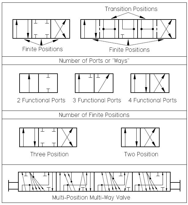
Mobile and Industrial Hydraulic Valves and Systems: Directional Control

Patent US2849987 - Hydraulic valve operator control system - Google

Hydraulic system circuit: 1 -motor; 2 -pump; 3 -reservoir; 4 -direct